| |
| Remove the screws from the 3 pedal plates |
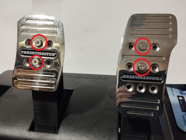 |
| Remove all the screws in the image. Be careful that there is a screw under the pedal cable. |
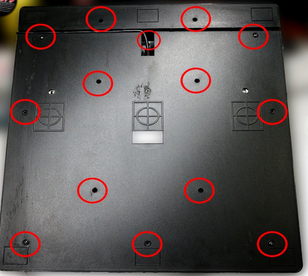 |
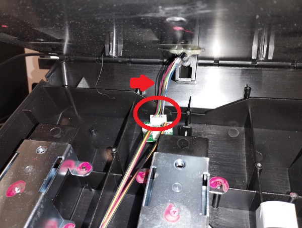
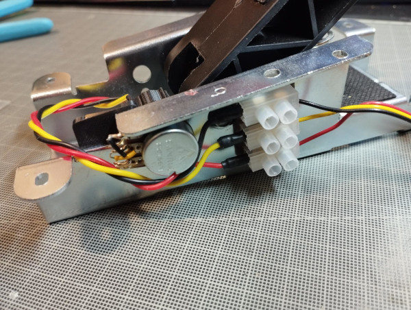
Remove the pedal board cable connector to be able to remove the pedal board cover. |
|
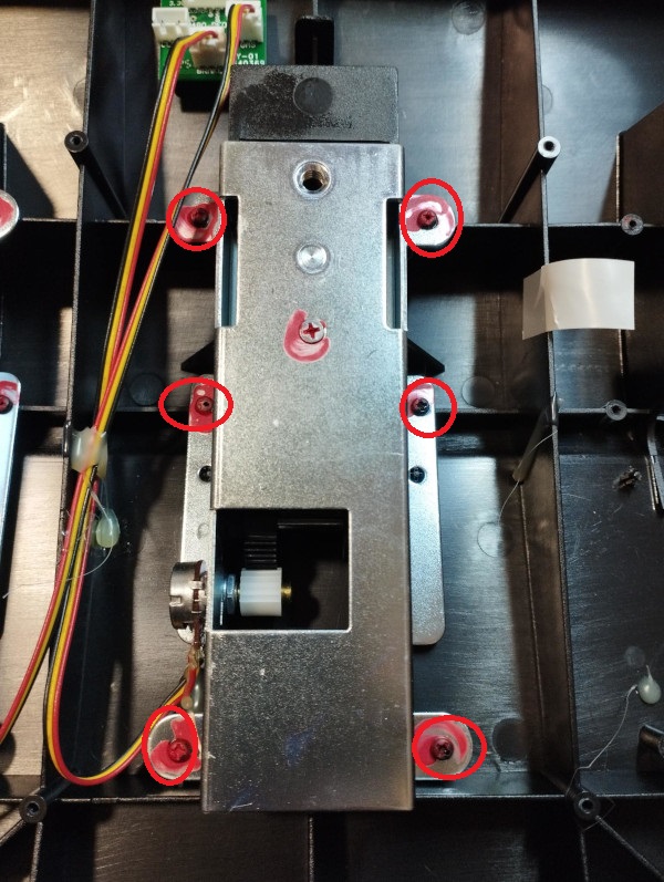
| Once the cover is removed, the pedal screws can be removed. |
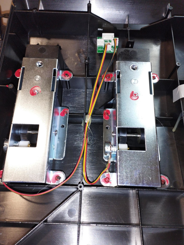 |
| Remove the 6 pedal screws. |
|
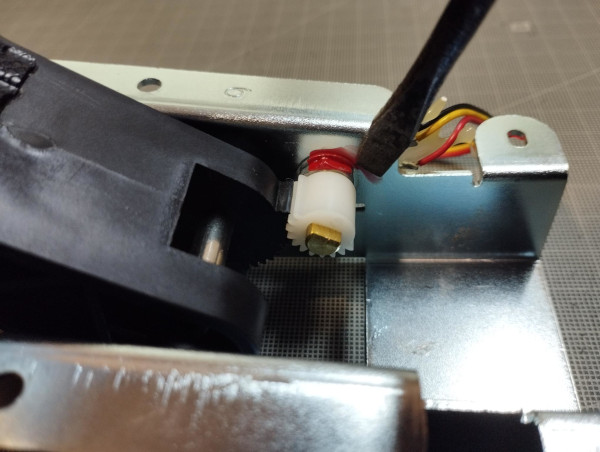
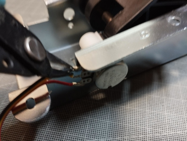
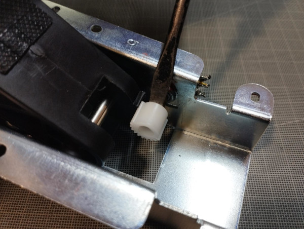
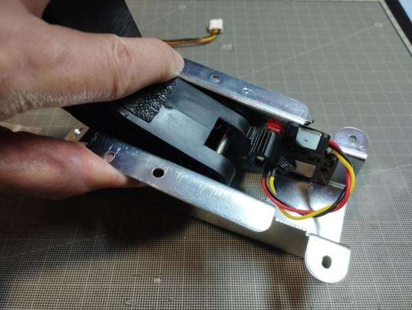
| Remove the red putty around the potentiometer with a flat screwdriver. |
|
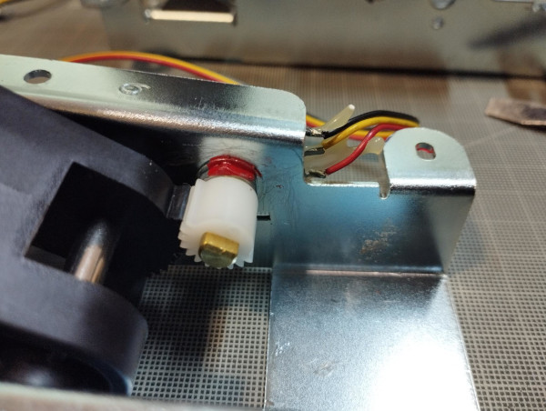
| The area around the potentiometer must be clean. |
|
| Cut the three wires of the potentiometer. |
|
| Strip the three wires. |
|
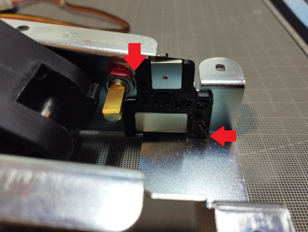
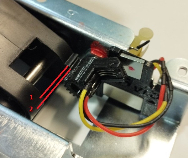
| Place the magnet piece touching the potentiometer nut and touching the pedal floor. |
|
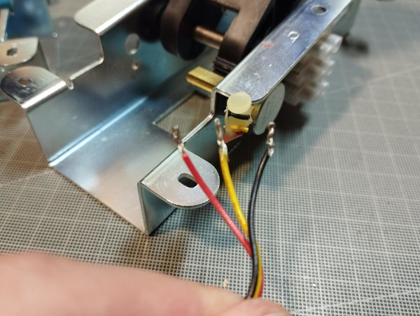
| Join the red wire of the connector with the red wire of the sensor, the black wire of the connector with the black wire of the sensor and the yellow wire of the connector with the yellow wire of the sensor. |
|
| Remove the toothed piece from the potentiometer with a flat screwdriver. |
|
| Glue the strip on the side of the pedal next to the potentiometer. |
|
| Insert the toothed sensor into the potentiometer shaft, leaving 2 teeth of the pedal visible from the top. Insert it all the way in. |
|
| Take the pedal and hold it a little tight so that the sensor teeth do not come out of their correct position and screw the pedal back on and connect the pedal cable to its connector. |
 |
| Put the covers back on and screw everything back on. |
| CARE!! Connect the pedal board cable to the base of the Thrusmaster pedal and disconnect the base from the socket (remove the power) and reconnect it, so that the base resets and recalibrates the new values offered by the pedal. |
| |
| Pedal Calibration with DIView |
If the steering wheel base does not self-calibrate, manual calibration of the pedals may be necessary.
Program download -> DOWNLOAD |
|
| |